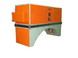
- A harmonic filter is used to eliminate the harmonic distortion caused by appliances. Harmonics are currents and Voltages that are continuous multiples of the fundamental frequency of 50Hz such as 100 Hz ( 2nd harmonic) and 250 Hz ( 5th harmonic)
- An increasing number of loads are non- linear, introducing harmonics into the power gird and thus significantly impairing the power quality. An active harmonic filter that effectively reduces the unwanted harmonics.
- Active power factor correction also markedly diminishes total harmonics, automatically corrects for AC input voltage, and is capable of a full range of input voltage. Since active PFC is the more complex method of Power Factor Correction, it is more expensive to produce an Active PFC power supply than PFC. Moreover, PFC has improved the power factor, But PFC is itself generating harmonic.
- Harmonics are caused by non- linear loads, that is loads that draw a non – sinusoidal current from a sinusoidal voltage source. Some examples of harmonic producing loads are electric arc furnaces, static VAR compensators, inverters, DC converters, switch-mode power supplies, and AC or DC motor drives.
- Connection Method: 3 phase, 4 wire, 50 /60 Hz ±5%
Railways
Industrial
Shop
- Nominal Input Voltage: 890 V AC, Three Phase
- Input Frequency: 50 Hz
- Output Voltage: 1200VDC
- Output Current: 3800 A
- Size (WxDxH): 853mm X 1037mm X 1450mm
- Panel with surge arrester, current sensor, contractor, capacitor etc.
- Equipped with all necessary protection device for locomotive auxiliary equipment
- Side window for inspection and easy maintenance
- Marking of each wire for identification
- 110VDC
- Equipped with all necessary protection device for locomotive auxiliary equipment
- Provide interface between control electronics and other devices
- Equipped with switchgear for battery charger, DC-DC converter, earthing fault, fire detection etc.
- Easy front access to all the devices fitted in the panel
- Front side glass window for inspection
- Equipped with all necessary protection device for locomotive auxiliary equipment
- Equipped with switchgear for Machine Room Blower, Compressor, Crew Fan, Cab Heater, earthing fault.
- Easy front access to all the devices fitted in the panel
- Front side glass window for inspection and easy maintenance.
- 110VDC
- 415VAC,50Hz.
- Equipped with all necessary protection device for locomotive auxiliary equipment
- Equipped with switchgear for Machine Room Blower, Compressor, Crew Fan, Cab Heater, earthing fault.
- Easy front access to all the devices fitted in the panel
- Front side glass window for inspection and easy maintenance
- 110VDC
- For main distribution panel between driver desk controls units and auxiliary control cubicle ,wago connector and circular connector used.
- 110VAC
- 110VDC
- 48VDC
- 24VDC
- EOG AC Coaches/Power car/Pantry car requires 750V/415V step down transformer for coach power supply.
- Their capacity requirement is 60 kVA and these transformers are mounted underslung.
- Nominal Input:60 kVA
- Voltage:3 phase , 4 Wire, 750 V ± 5% (line to line), 50 Hz ±3%, THD < 10%
- Output: 415 VAC
- The aim of this document is to brief the technical description and necessity of the mobile battery charging unit of SSK Class Batteries (Type-II) MRLC Project and Scorpene class Submarine Batteries (Type-IV) of Project-75.
- The main function of said unit is to charge batteries of propulsion system of the submarine.
- Electronic Controlled pneumatic Brake controller consists of electronic charging Discharging Valve for Brake Pipe and Brake cylinder. The panel has additional Fully Mechanically operated valve for failsafe operation at the time of Electronic Failure. The mechanically operated valves can operate brake system at the time of power failure and fully complied with UIC540
- Electronic Brake Handle (both Loco Brake SA9 and Formation Brake handle A9). 2 x 20 based LCD display is available for showing different fault status and mode of operation etc
- Auxiliary Pneumatic Panel for Controlling Feed Pipe, Pantograph, VCB, Unloader, Sander etc
- Electronic Vigilance Control Computer
- Soft PLC based Computer for controlling overall brake system. It consists of multiple Digital and Analog 10 Cards with ARM Processor based cards. Communication Protocols used are CAN for backbone real-time communication, Ethernet for Diagnostic Data, RS485 and RS232 for additional communication.
- Connection: Single
- Input Voltage : 1222VAC
- Output Current : 3300 ADC
- Output Voltage : 750 VDC
- Power : 5400 kVA