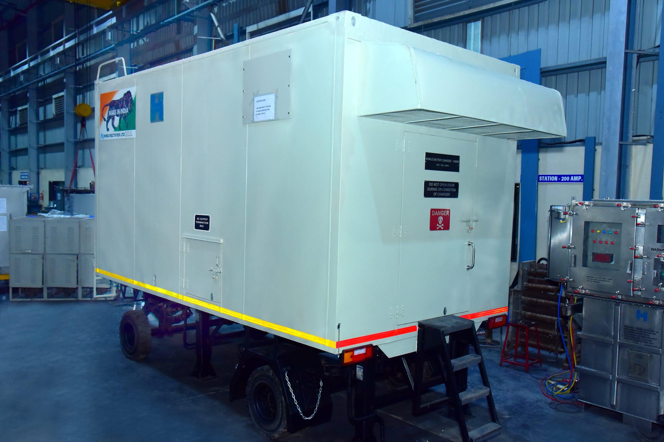
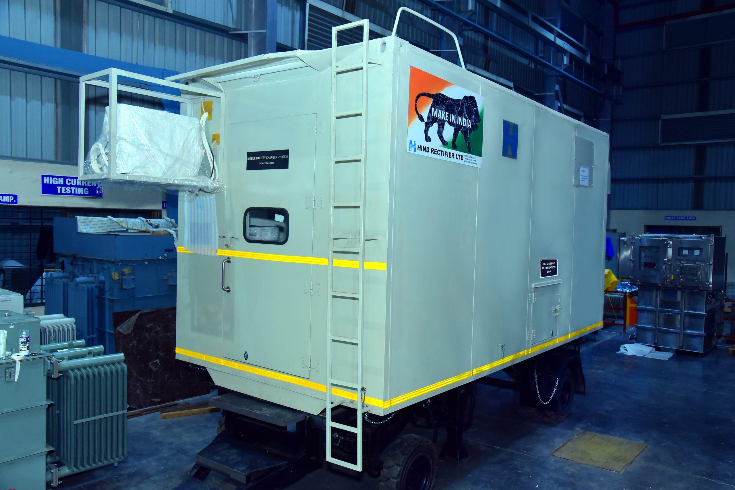
Battery Charger for Submarine
1) Objective:
- The aim of this document is to brief the technical description and necessity of the mobile battery charging unit of SSK Class Batteries (Type-II) MRLC Project and Scorpene class Submarine Batteries (Type-IV) of Project-75.
- The main function of said unit is to charge batteries of propulsion system of the submarine.
2) Scope of supply:
a) Mobile battery charging unit-01 No. b) 3 years’ on-site warranty of equipment
c) Special tools-Mandatory tool to be provided by Vendor for carrying out the preventive &
breakdown maintenance. d) Vendor has to be submit budgetary quote of recommended spares with validity up to 3 years
3) General technical description:
This unit is to be used for charging of the SSK’ class (Operating Voltages 200-360 V DC) & ‘Scorpene’ class (Operating Voltages 380-520 V DC) submarine propulsion batteries in the
shipyard
3.1) Input Power Source
a) Rated AC Voltage 415 V +/-5% b) Rated Frequency: 50 Hz +/- 2% c) No of Phases: 3 phase (4 wires)
d) Protection Connection cell MT motor driven circuit breaker MT
Note: In built Transformer should have efficiency more than 98 %. Test certificate of transformer shall be provided along with the unit.
3.2) Output Power
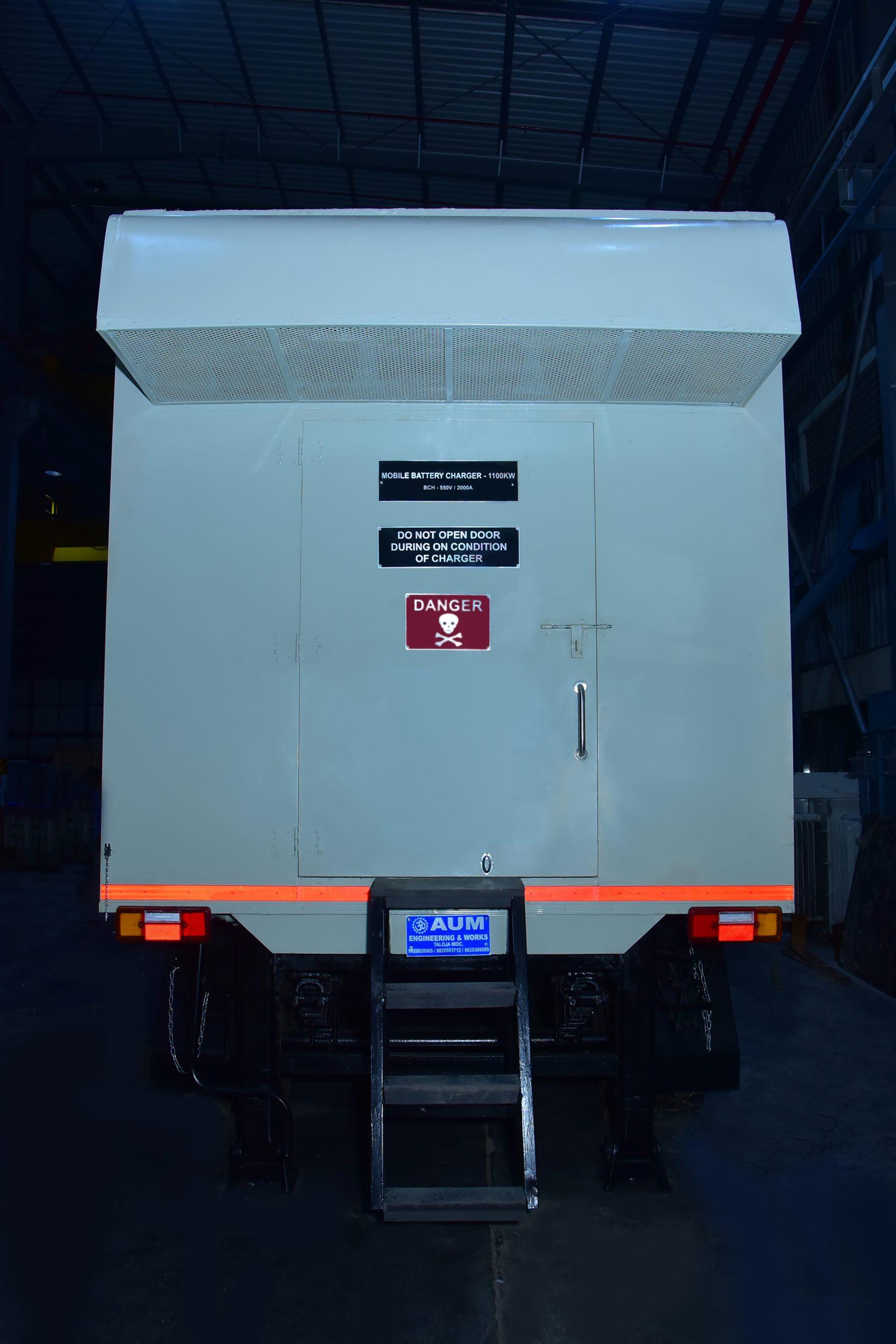
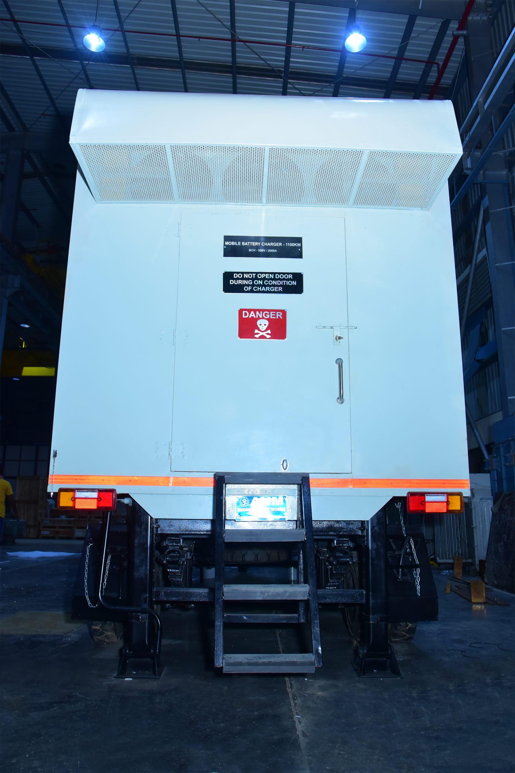
a) Rated Output DC Voltages :0-550 V
b) Rated Output DC Current: Adjustable 0 to 2000 A c) Rating Class: Continuous.
d) Ripple: Less than 3 % RMS at full load.
e) In CC Mode: Constant Current regulation is +/- 1%.
f) In CV Mode: Constant Voltage regulation is +/-1%.
g) Protection: Motor driven Circuit breaker at output to isolate On-board Batteries and Charger.
3.3) Control Characteristics:
a) Rectifying Circuit System: 2 no. of 3 Phase full wave fully controlled 6-pulse Bridge forming a 12-pulse rectification. b) Output adjusting system: Thyristor phase control.
3.4) Protections:
a) Incoming ACB.
b) Over voltage suppression circuit/Input RC surge suppression.
c) Output under/over voltage tripping system. d) Negative sequence and single phasing protection on input side.
e) Current trip for instantaneous and average over current tripping by electronic sensing. f) dv/dt protection for thyristor.
8) Semiconductor fuses for thyristor.
h) Thermostat for over temperature protection of transformer and critical devices.
i) Equipment should be equipped with Emergency push button which will trip the unit, input and
output breaker in emergency condition.
3.5) Place of Installation: Indoor/Outdoor
3.6) Earthing: A copper ground wire will be provided inside the panel. All metal parts will be earthed to this ground point. The common earthing point will be brought out of the panel by suitable bolt.
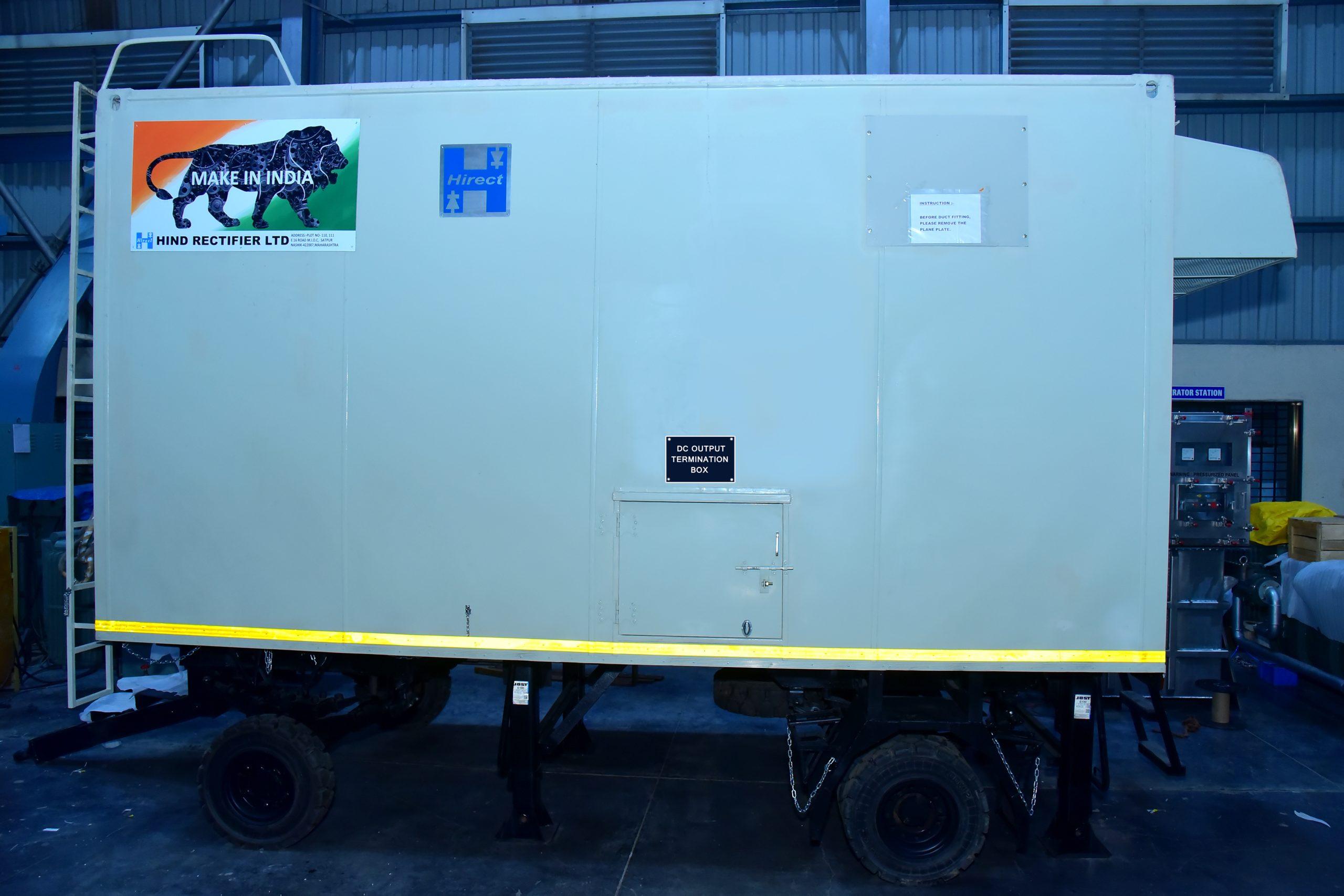
3.7) Cable entry: Input and Output cable entry from bottom and termination accessible from side. There should be provision of enough space to be made in terminal box for termination. Earthing studs to be provided at both the terminal box.
3.8) Metering:
a) Input AC Voltmeter/Ammeter with selector switch: 0-600 V, 0-2500 A (Analog) b) Phase sequence meter: Rotating Disk type indicator with push button.
c) DC Ammeter, Power, Voltmeter: 0-800 DC V, 0-2500 A DC (Digital)
d) Ah meter.
e) Digital Power Manager.. f) Digital Online Insulation meter at output side to monitor the insulation level of Power as well
as control circuit. (Measurement between positive to ground and negative to ground)